Stereoscopic CAD on LiDAR & oriented surfaces
StereoCloud3D streams massive LiDAR and photogrammetric point clouds in real time and lets you digitize precise CAD features in true stereoscopic 3D — from cartographic terrain to vertical facades, bridge faces, dam fronts and inclined roofs. Work with georeferenced imagery underlays, limit streaming with Cloud AOI, and place vertices on the cloud surface with AUTO-Z and Cloud Z snap.
Watch it work
Short screen recordings of StereoCloud3D 4.0, straight from the application. Each one is under a minute.
Create a new project in Stereo Cloud. Give your project a name and select the folder where the data is stored. Wait for the data upload and convert process. Once the import is complete, click OK and you are ready.
To zoom in or out, simply rotate the mouse wheel. To pan, click the mouse wheel. To rotate in 3D view, press the G key, then hold Shift, click and hold the mouse wheel and move the mouse to rotate the view in 3D. Press T to return to a wider top view of the workspace. You can also right-click and select Zoom Window to zoom specifically into the area selected with the window.
StereoCloud3D features a professional CAD environment, including all the essential tools for drawing and editing. Another important menu is the Inspector, where you can customize your cursor and the main CAD elements. The toolbar menu is essential too, giving you access to all the toolbars and tools you need for your workflow.
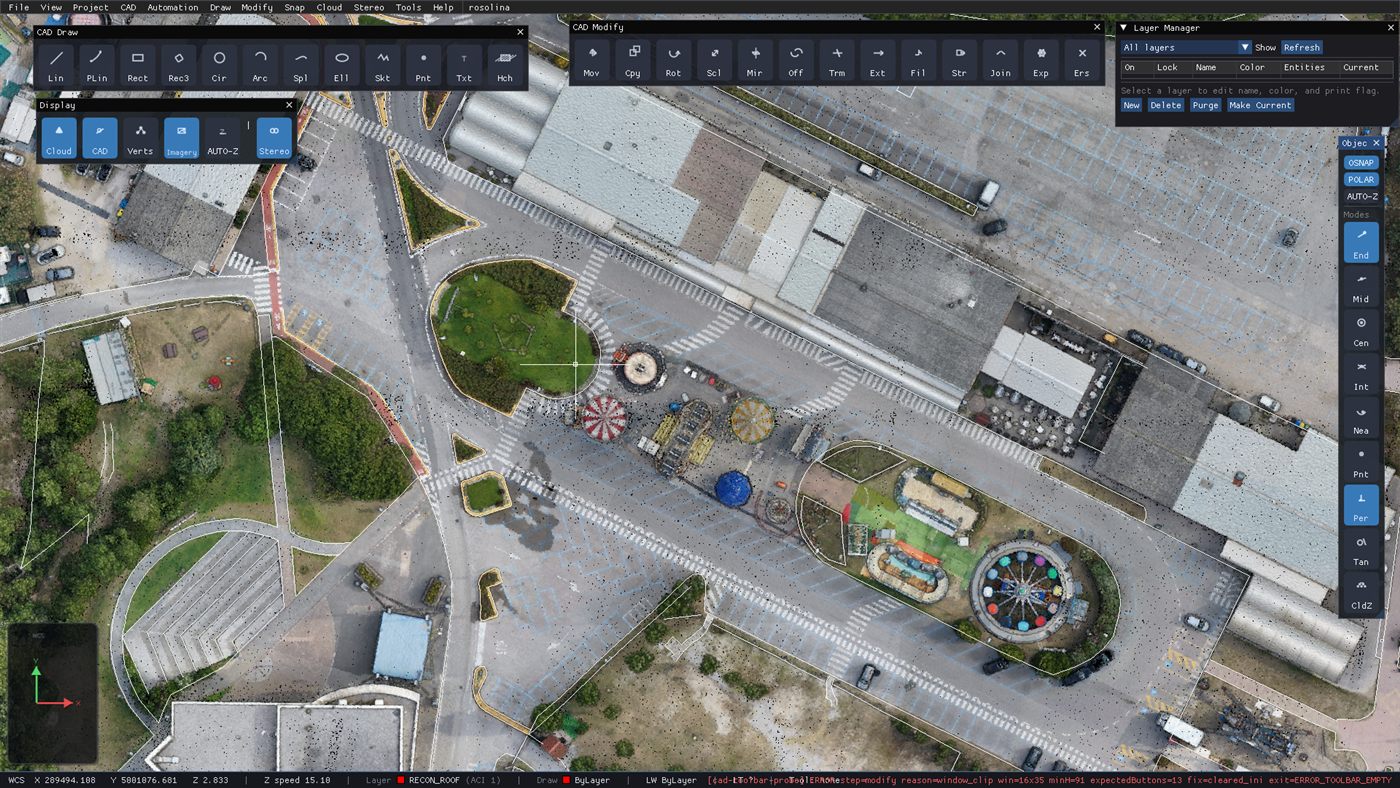
Another important feature of StereoCloud3D is the ability to use a geo-referenced orthophoto as a reference, for drawing details that are more clearly visible on the image than among the points.
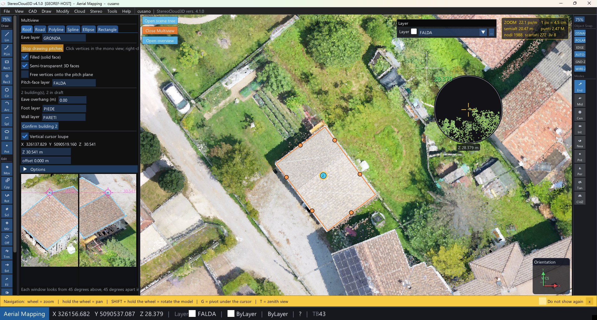
Multiview is a specialized interface for semi-automatic drawing of specific graphic elements. For roof planes, simply click along the eave contour: a magnified view of the area and two additional views on the left help you monitor each click point and ensure accurate positioning. The roof planes are automatically placed in 3D, then you complete the building by creating the entire solid and choose the colours you prefer.
In the stereo section, you can select from several different setups — mono, side-by-side on a dual monitor, PluraView on three monitors, or NVIDIA 3D Vision 2 active shutter. Confirm the display setup and apply.
Try the Z-exaggeration mode while working in stereoscopic view to enhance depth perception and make the 3D effect easier to see.
One document
Ten pages with the main features and the screenshots that go with them. Read it here in your browser, or keep a copy.
A4 landscape, 10 pages, about 2.8 MB. Covers cloud classification, georeferenced imagery, CAD on the cloud surface, roof pitches, Multiview, Stereo UCS and Z exaggeration, plus the work under way on overhead power lines. Company references and contacts are on the last page.
What it does
From raw LAS/LAZ to a finished, accurate vector deliverable — without leaving the 3D model.
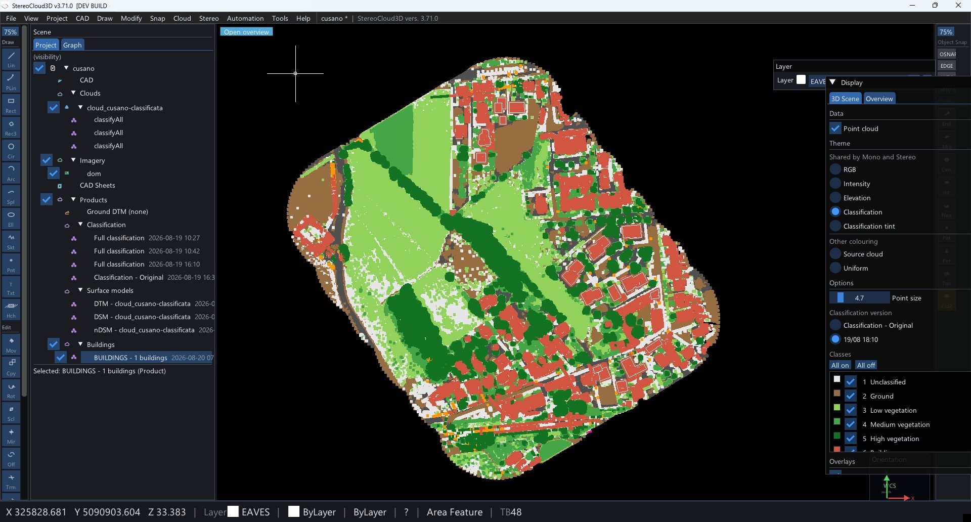
Write standard ASPRS classes into the cloud — ground, buildings, roads, water, poles, wires, vegetation — in one run with a terrain preset, and get DTM, DSM and nDSM rasters out of the same pass. A backup taken first makes it reversible.
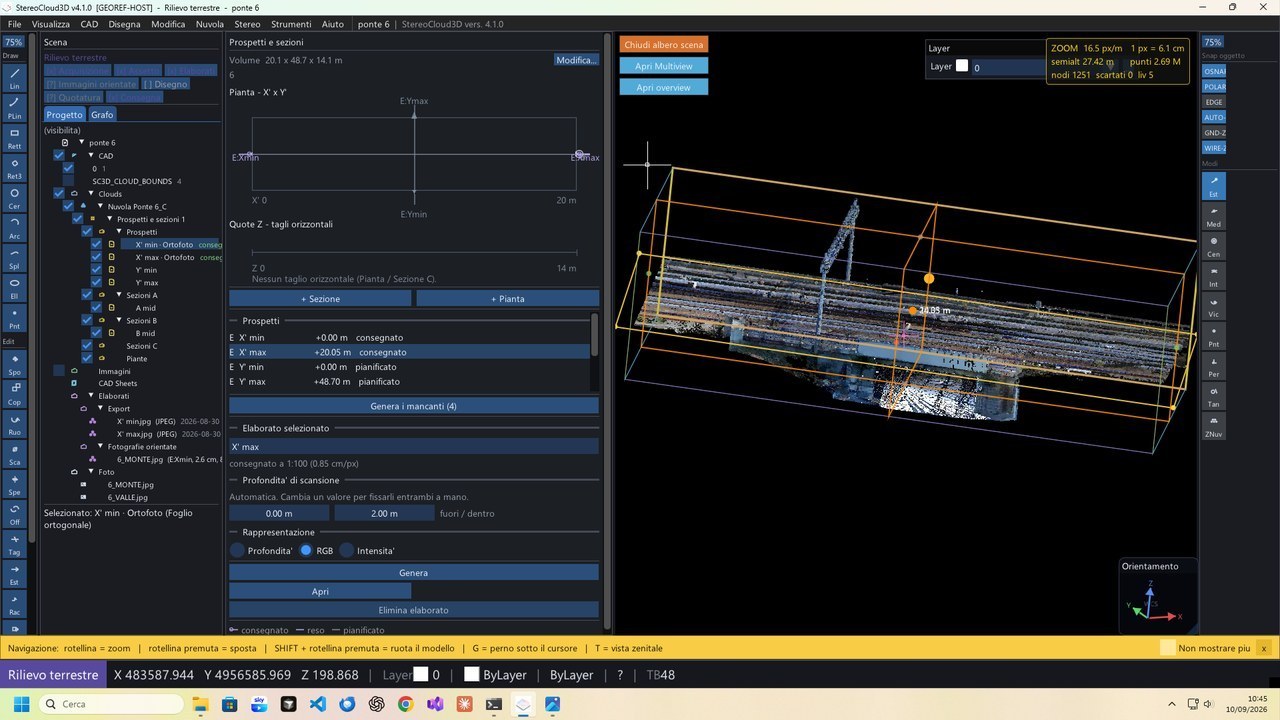
A work box aligned to the object, not to north, yields plans, four elevations and any section you cut — each one an orthophoto rasterised from the points themselves, so no photography is needed.
Compose the deliverable on a CAD sheet: paper size, scale 1:N, the definitive orthophoto generated at that scale and DPI, placed and cropped, your CAD on top, exported to DXF or DWG.
NVIDIA dropped 3D Vision in 2019 and no current card runs that driver. StereoCloud3D drives the emitter itself over USB and alternates the eyes on a 120 Hz panel, so the shutter glasses already on your desk go back to work — full resolution to each eye, no NVIDIA stereo software involved.
Install QGIS Long Term once (free). Then import .ecw like any other
raster — you never open QGIS; StereoCloud3D converts it to a GeoTIFF inside the
project. Imagery layers live in the Scene Tree.
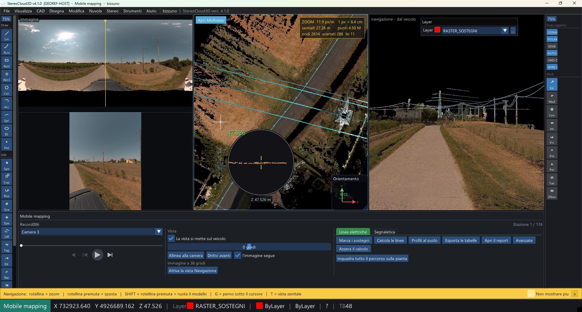
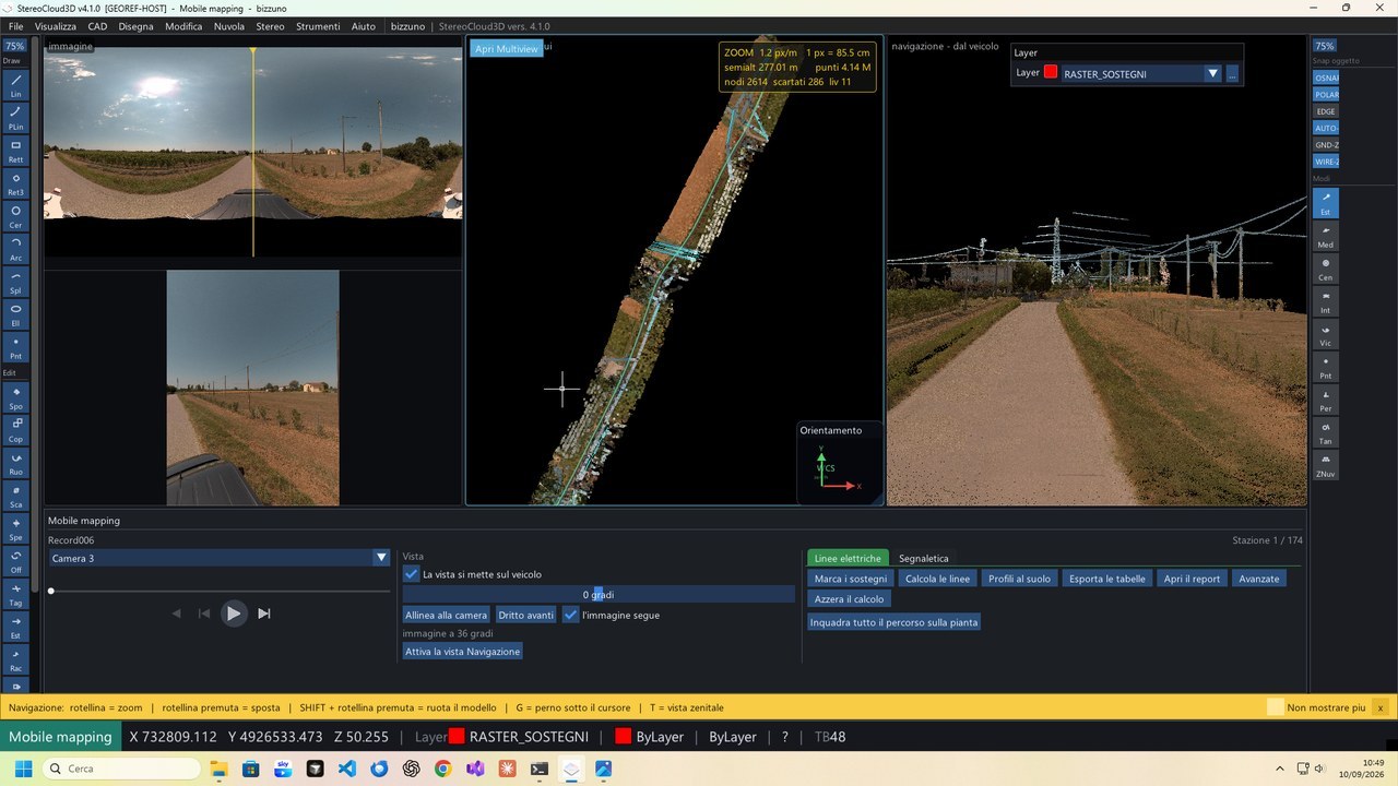
Inside a Cloud AOI the overhead wires come back as 3D polylines that follow the real sag, not straight lines between poles. What tells a wire from a gutter is the empty space around it, and every span is reported with its length, height above ground, sag and measured thickness — so you check the proposal before it reaches the drawing.
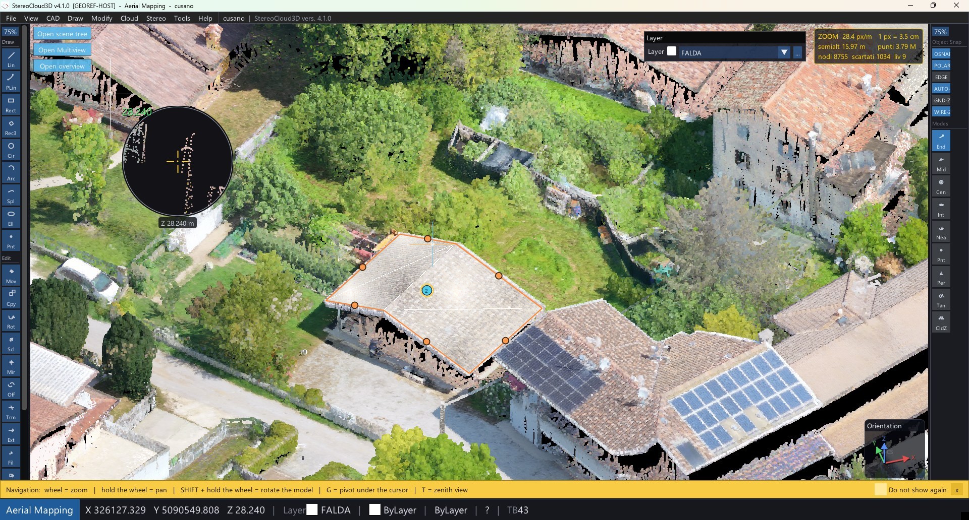
Draw the roof outline, then the ridge and the hips, and StereoCloud3D builds the roof pitches from them as a single mesh — adjacent pitches share the same edge, so no crack can open between them — and closes the walls down to the ground height you measured. The surfaces are filled, lit and exported to DXF as a real mesh.
Pick a building and get a zenith view plus four oblique views taken around it. You draw the outline once — it lives once in 3D and appears in the others by projection. The zenith fixes the plan, the obliques fix the height, the cloud gives the roof and the ground. Full 3D restitution on an ordinary monitor.
Tiled level-of-detail streaming keeps clouds of hundreds of millions to billions of points smooth on ordinary workstations.
Every desk layout is supported and listed: dual-monitor side-by-side, PluraView beam-splitter at full resolution per eye, and NVIDIA 3D Vision 2 active shutter. The main window keeps menus and a mono reference view, plus a dedicated Navigation view for flying over the model.
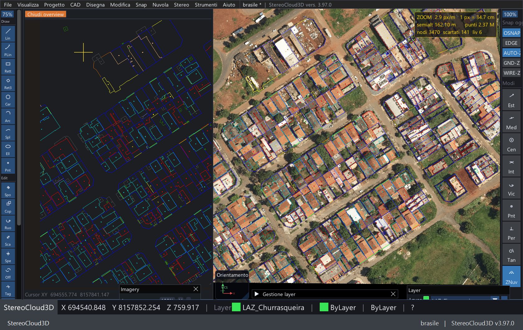
Lines, polylines, breaklines, contours, building outlines and more — with AUTO-Z and Cloud Z snap so elevation follows the live cloud surface.
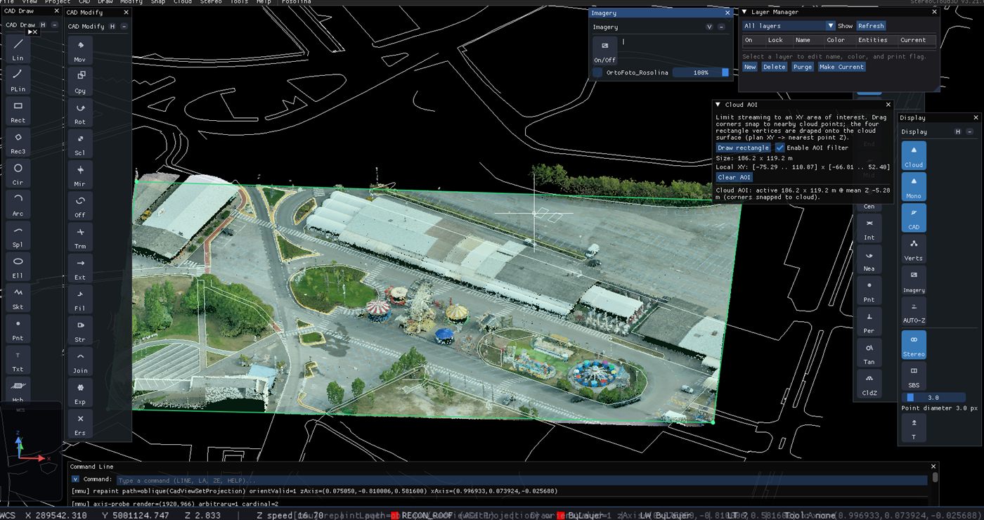
Draw an XY area of interest to limit streaming to the zone you are working on. The AOI drapes on the cloud, follows pan, and is stored in the project.
Import georeferenced orthophotos (GeoTIFF, ECW, JPEG, PNG) from the Scene Tree or Project Manager. ECW needs a one-time free QGIS LTR install; StereoCloud3D converts the file in the background. Toggle visibility and opacity from the Imagery toolbar.
Align the view to vertical walls, bridge faces, dam fronts or custom inclined planes — digitize in stereo directly on TLS and dense 3D clouds.
Automatically seed a grid of spot heights sampled from the cloud, with spike removal and stereo verification.
One control trades crispness for fluidity, so huge scenes stay responsive on any GPU — Fast, Balanced or Quality.
Compose a project from an existing project, cloud folder, imagery and CAD drawing. Queue LAS/LAZ to tile indexes in the Cloud Batch Converter without blocking CAD.
Pick any point on the cloud with G, then rotate with Shift+MMB or a trackball for yaw/pitch, and Ctrl+Shift+MMB for roll.
Versioned drawing backups on save, restore from backup, and input recovery tools so a stuck pan or orbit never blocks production.
Per-project reports: operator, time worked, points used, entities produced and dataset sizes.
Production UI
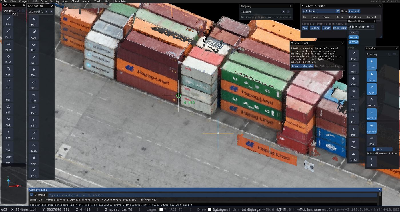
Floating CAD Draw / Modify toolbars, Layer Manager, Object Snap, Display toggles and a classic command line sit around a full-resolution viewport. Switch Cloud, CAD, Imagery and Stereo without leaving the scene.

Massive clouds, fluid navigation
A streaming tile engine loads only what is visible, at a resolution matched to your zoom. Pan and zoom stay smooth even on 1.5 billion-point scenes; a crisp full-resolution pass renders the instant you stop.
One run, every class
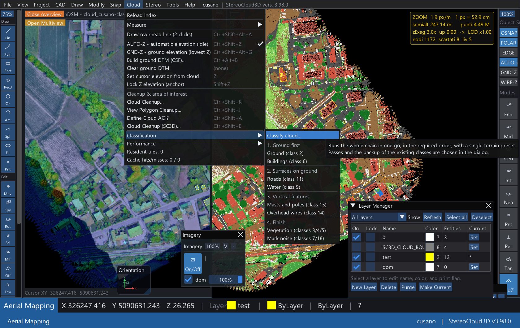
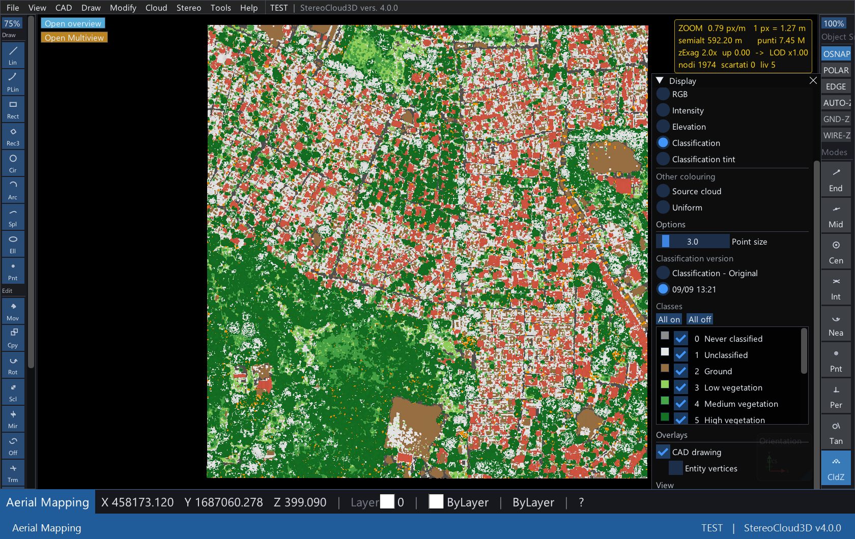
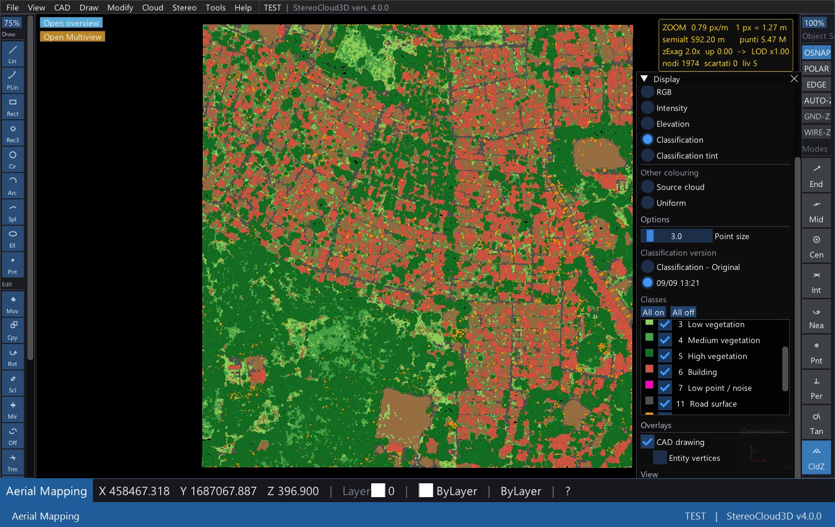
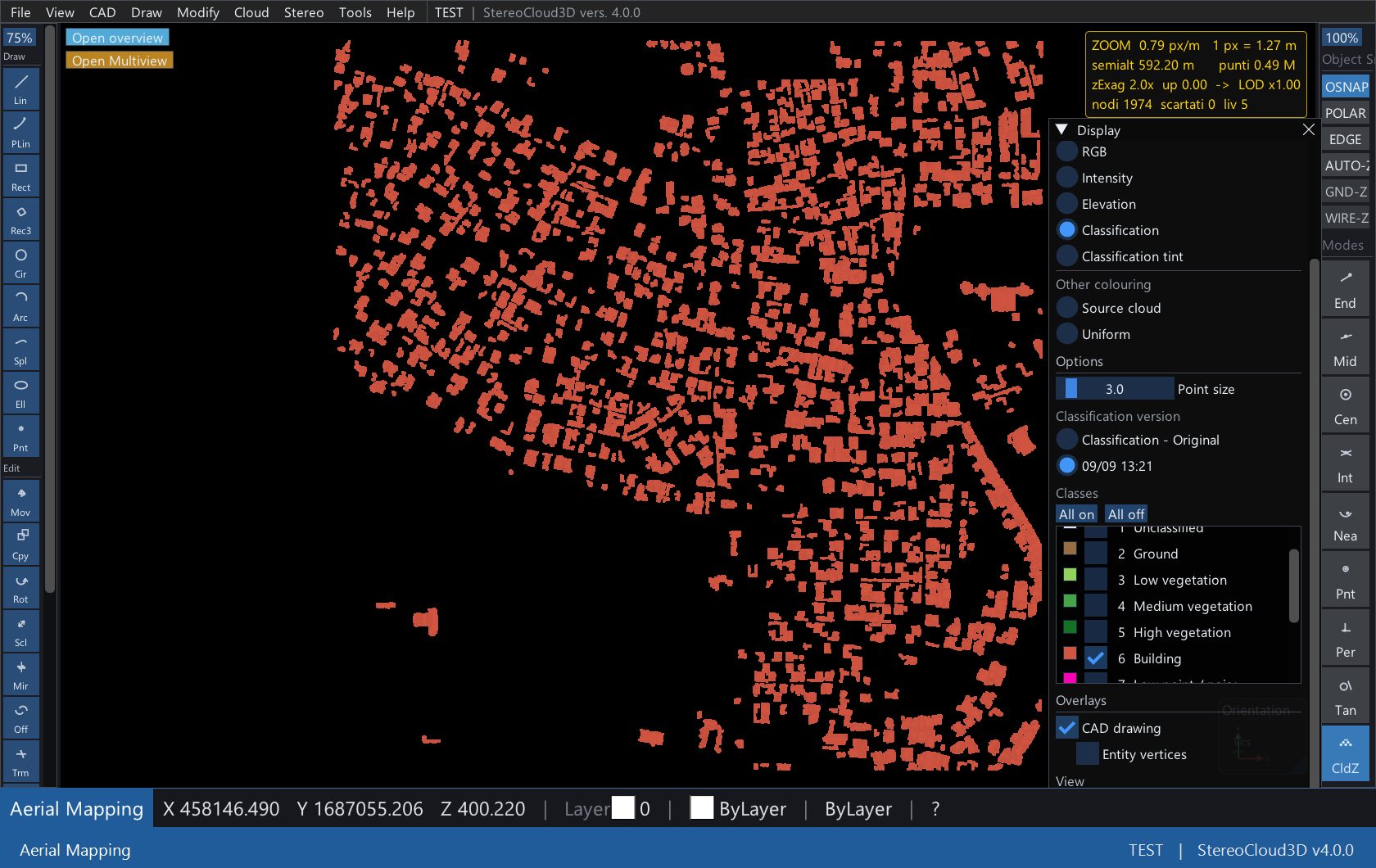
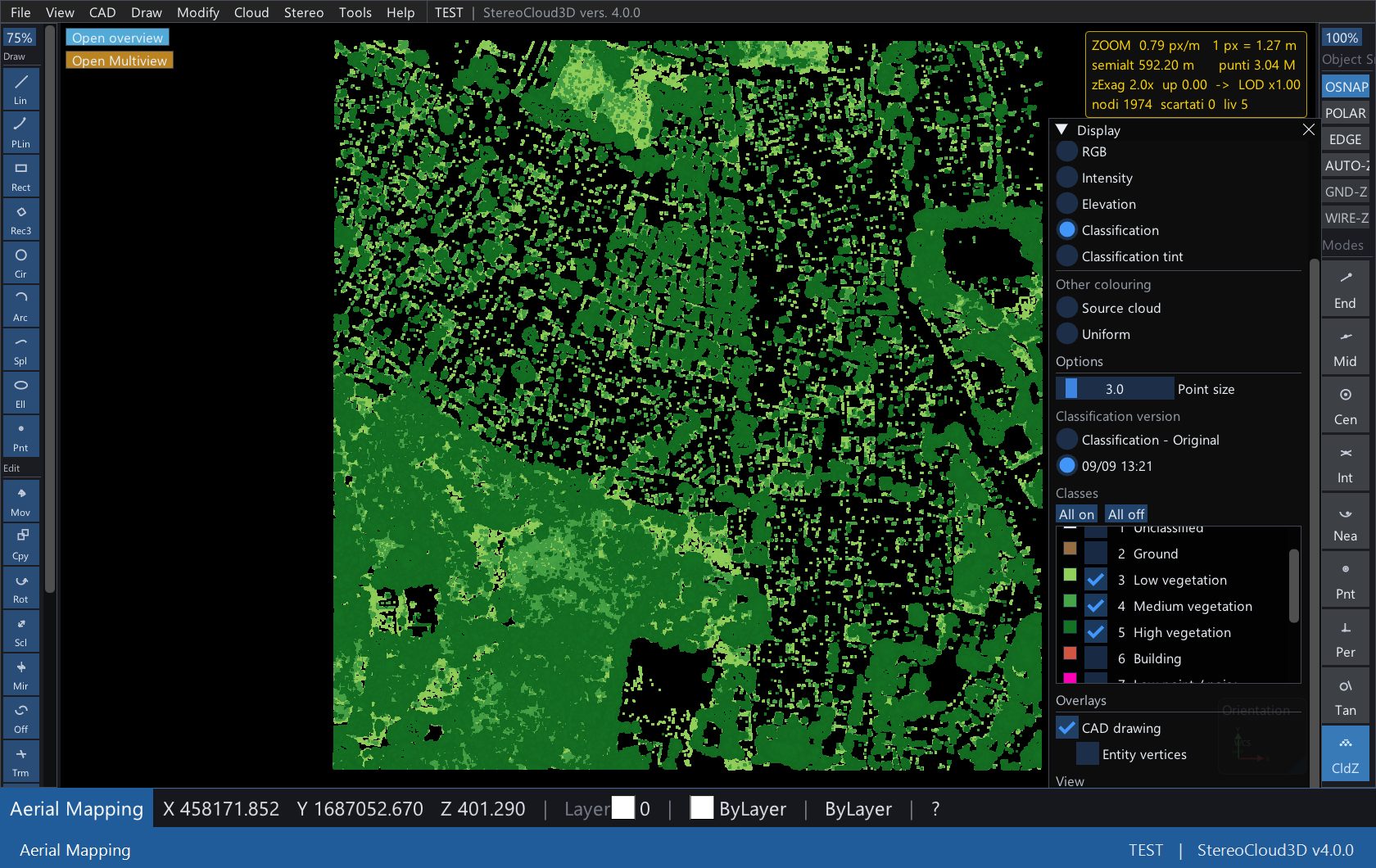
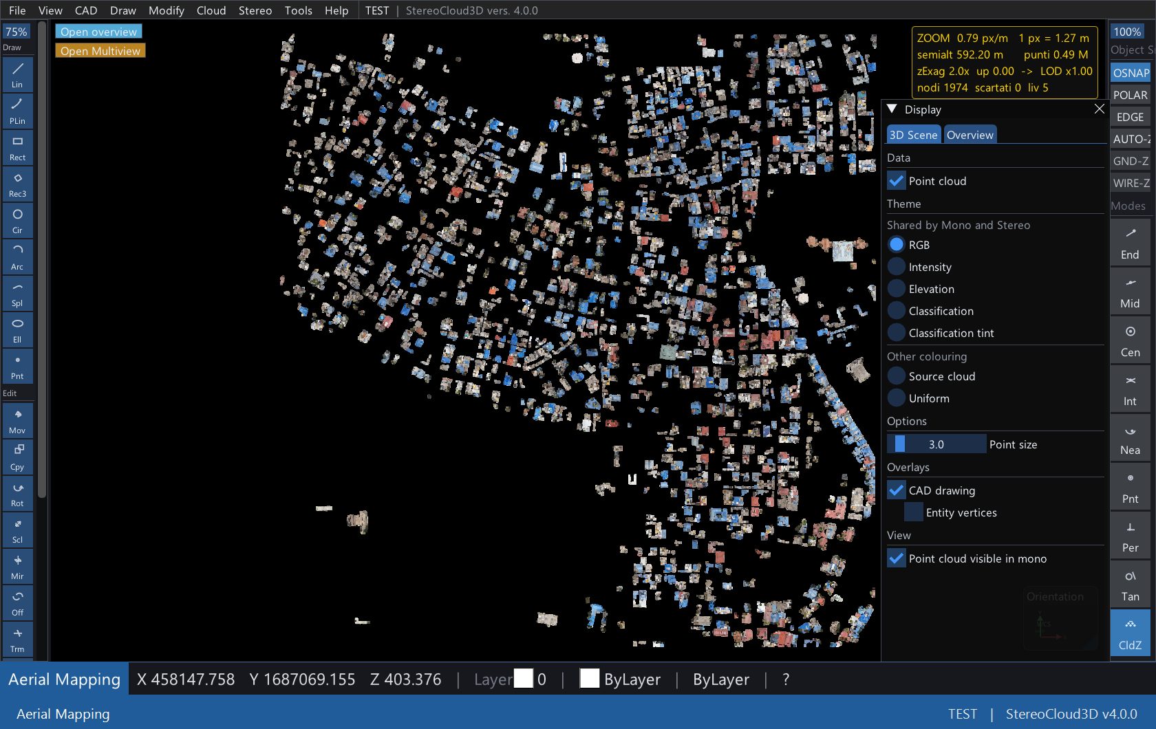
Start the whole chain from one dialog and let it run: ground first, then buildings, surfaces on the ground, vertical features and vegetation — standard ASPRS classes written into the cloud with a terrain preset. The existing classes are backed up before the run, so nothing is lost.
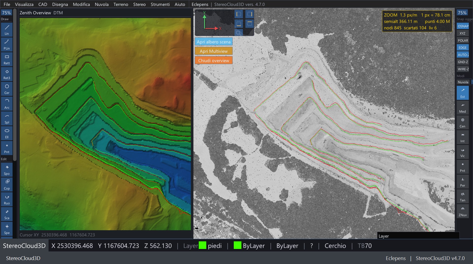
Terrain products
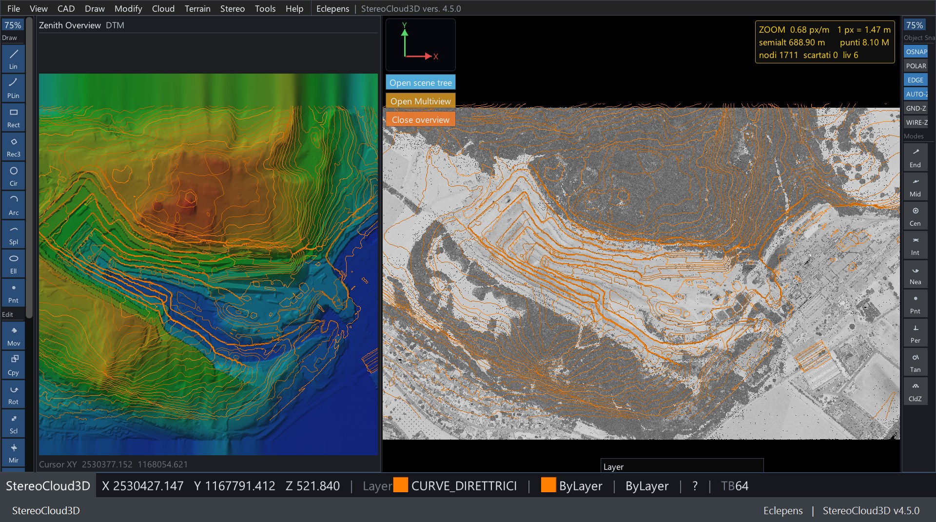
A classification run writes the terrain out as a raster of its own:
dtm.tif, built from the ground points alone with the holes filled, at
half-metre cells. Show it in the Zenith Overview and it is shaded under your drawing,
so the shape of the ground is in front of you while you digitize — and it becomes
the session terrain, the surface your elevations are read from.
Context under the vectors
Import orthophotos and raster backgrounds with GDAL, stream them inside the project, and keep their visibility synchronized with the CAD layer stack. Toggle and fade opacity from the Imagery toolbar without interrupting digitizing.
Always in sight
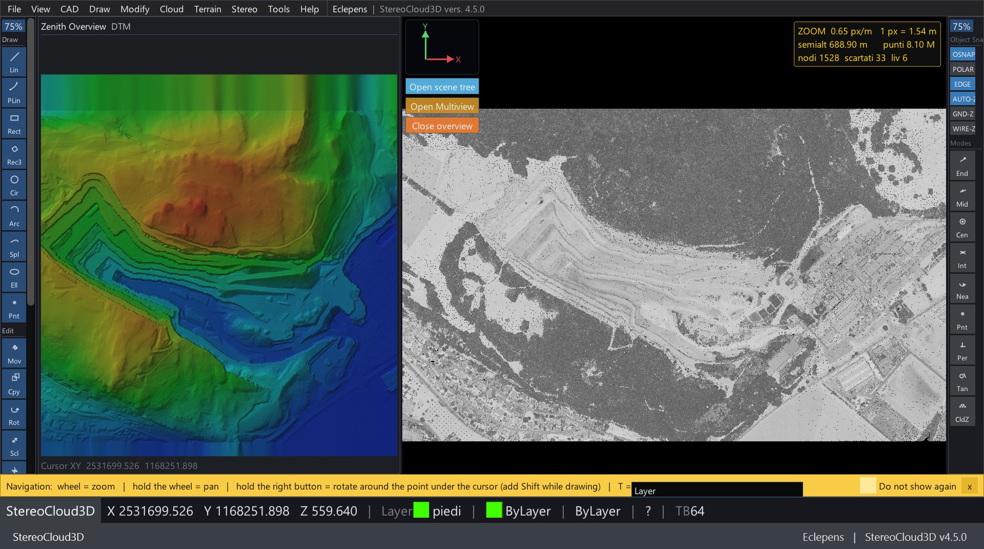
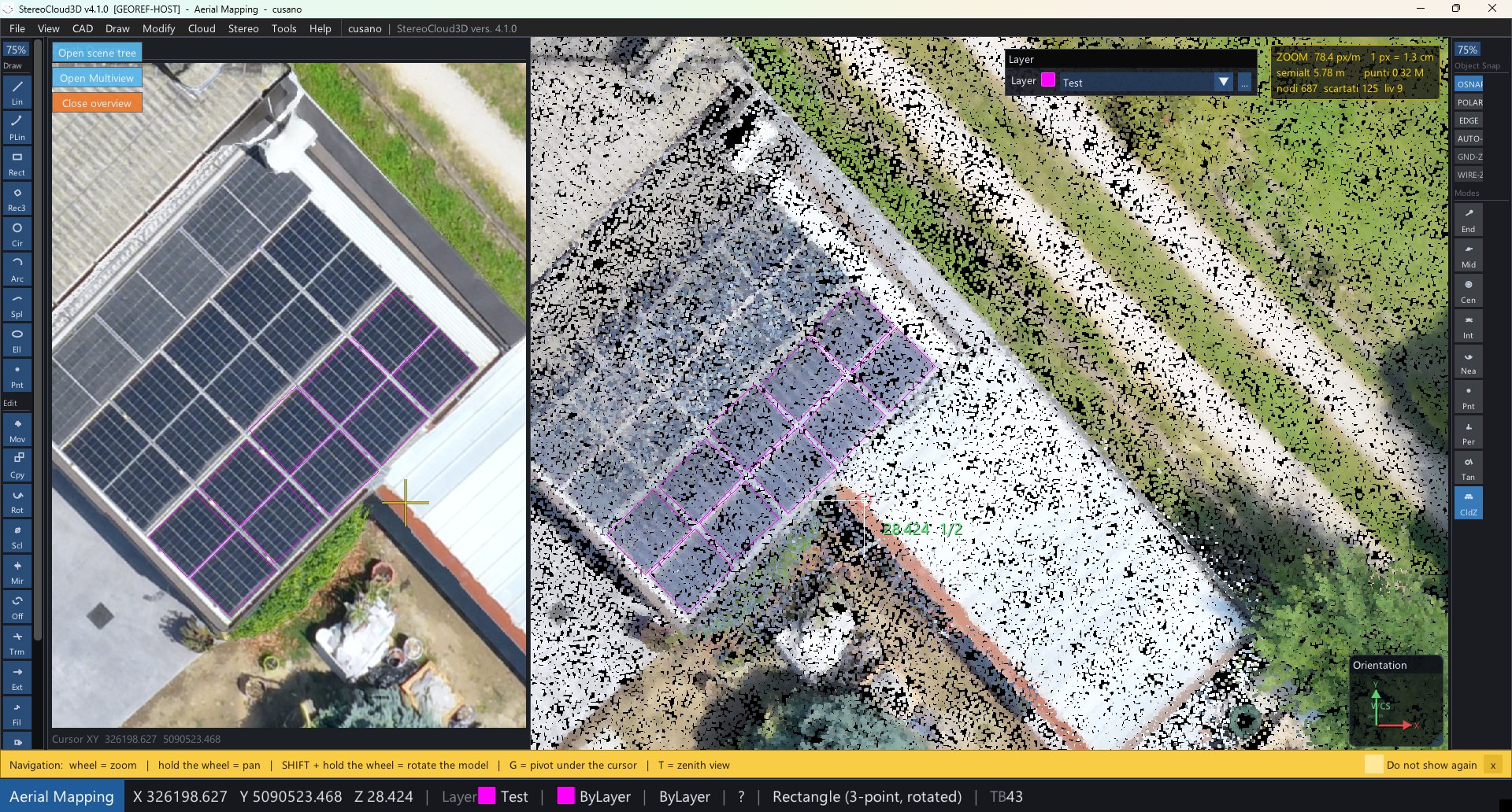
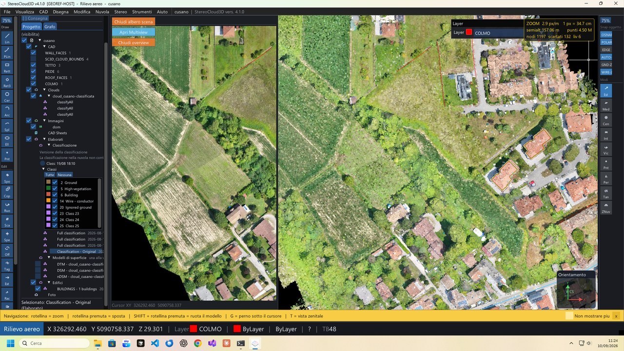
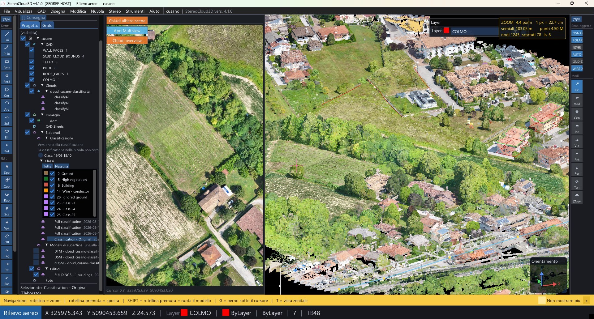
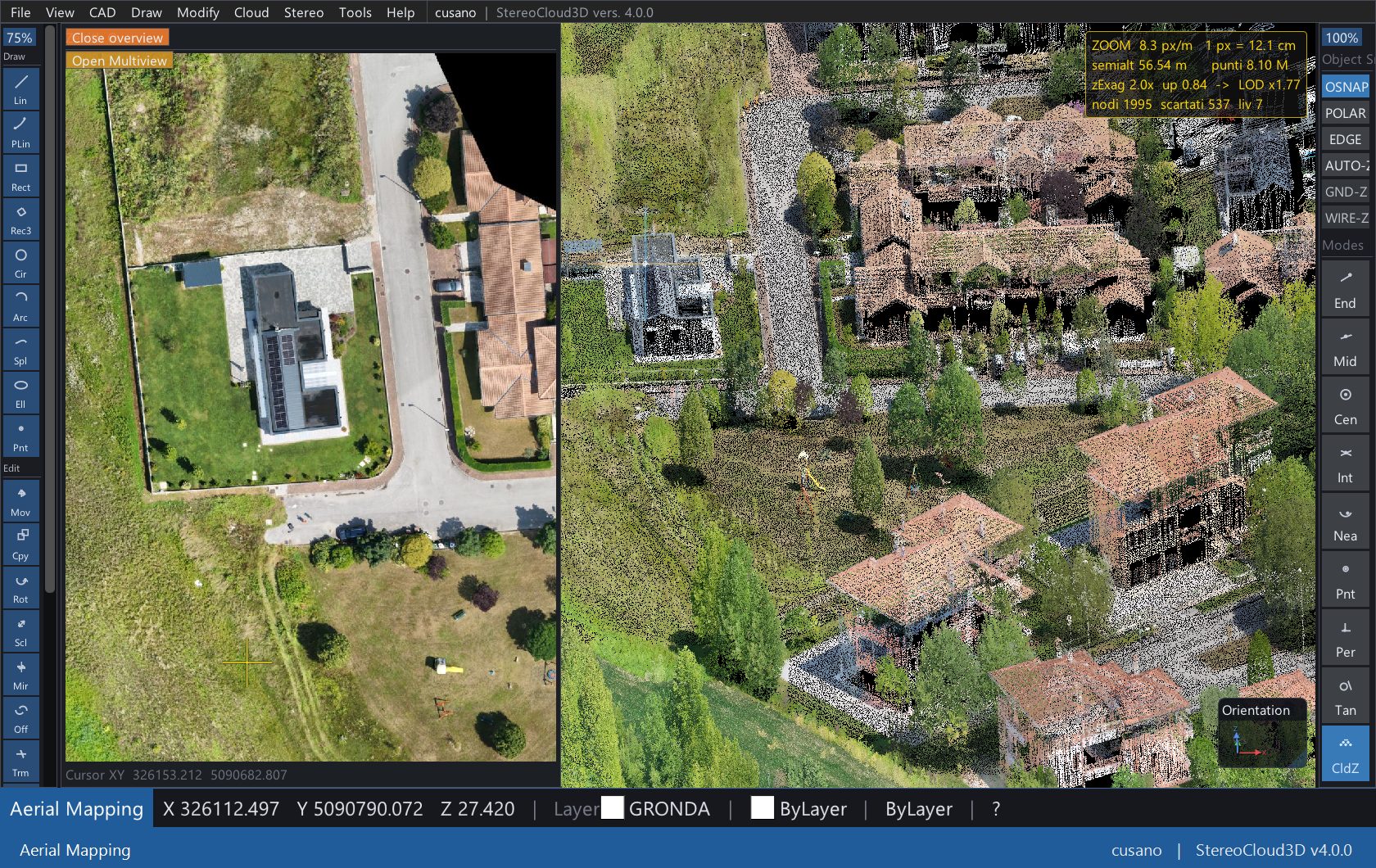
We built an Overview panel that shows the work you have already drawn while the main view stays down on the detail. Into that same panel you can load an orthophoto, and it becomes a useful reference exactly where the cloud is hard to read — so you always know what you are digitizing, even where the points alone do not tell you enough.
Focus streaming where you work
Cloud → Cloud AOI… (Ctrl+Shift+A) lets you draw an XY rectangle that limits cloud streaming to the area of interest. Corners drape on the cloud surface, the overlay follows MainMono pan, and the AOI is saved in the project manifest.
From cloud to deliverable
Digitize themed features with one-key macros, snap elevation with AUTO-Z or Cloud Z, manage layers and groups, and export to DXF. Versioned CAD backups and restore keep long sessions safe.
Assisted drawing
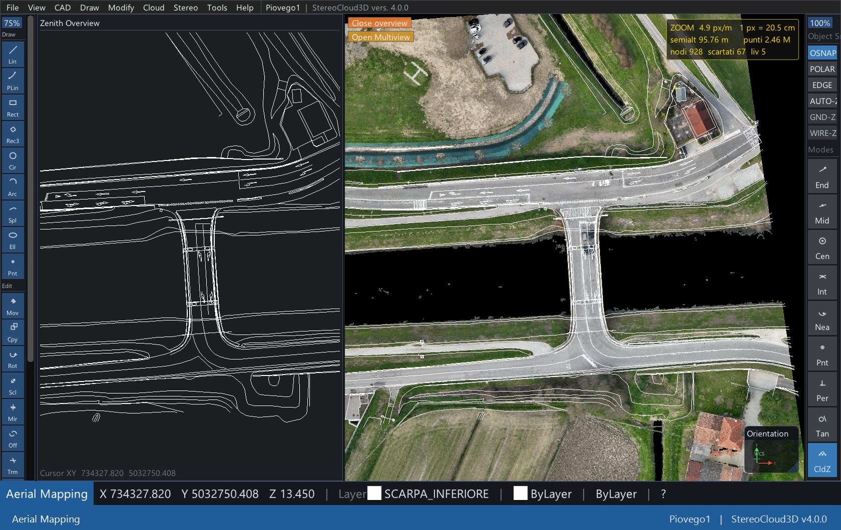
Drawing in the cloud and on its surface is assisted by a sophisticated CAD engine, so the vector deliverable comes together quickly instead of vertex by vertex. Every command you would expect is there — the Draw and Modify toolbars, circles, arcs and dimensions, object snaps, the Layer Manager and Entity Properties — and the view keeps up with you: rotate freely in 3D, pan and zoom without ever dropping the command you are in.
From outline to solid
Draw the outline, the ridge and the hips, and the pitches are built from them as one mesh. Every pitch then carries a dot on each vertex and a ring on each edge midpoint: drag one and everything welded to that point — adjacent pitches, eave, foot and walls — follows, so the building never comes apart.
No stereo hardware needed
Multiview shows the last point from two genuine photographic directions, chosen by scoring candidate bearings against the cloud so that both actually see it. The outlines you have already drawn are projected into both windows, with the part hidden behind the roof drawn faint — so a vertex is judged against the cloud around it, not against the drawing alone.
True depth, real accuracy
Perceive genuine relief and place vertices on the correct surface — ground, roof ridge or structure face — instead of guessing from a flat view. Adjustable parallax and a dedicated stereo cursor keep fusion comfortable on dual-pane and shutter hardware.
Stereo viewing
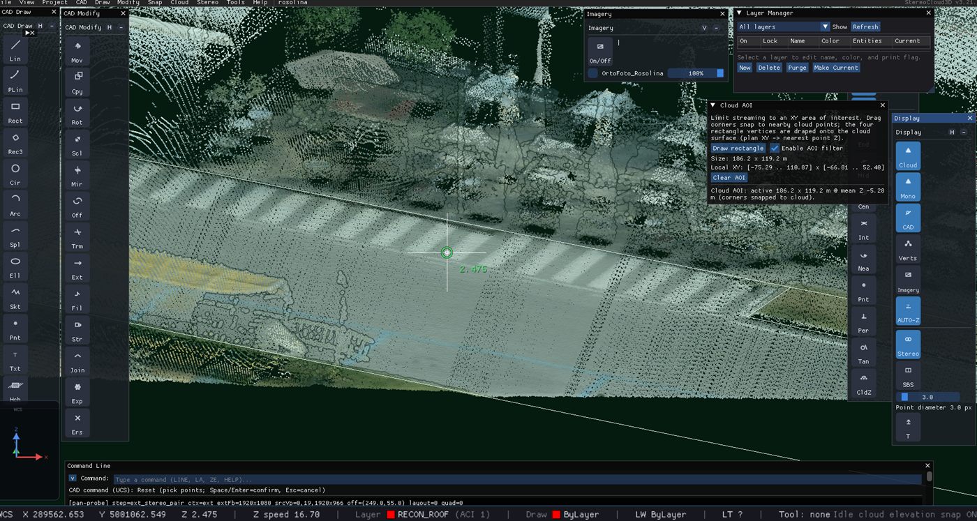
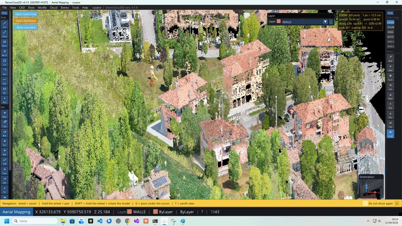
Stereo tells you where things sit in depth, but gentle ground can still read almost flat. Z exaggeration multiplies the vertical scale of the view: the stereo separation grows with it, and changes in elevation become far easier to see — a slope, a kerb, a shallow ditch, the fall of a roof. The scene is stretched on screen only: coordinates, measurements and everything you digitize keep their true elevations.
zExag 3.0x, and appears only while it is on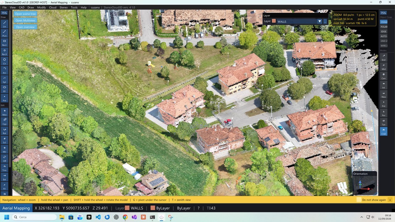
Supported 3D display classes
StereoCloud3D maps your workstation to a neutral profile — no vendor-specific setup in the product UI. The main window always keeps menus and a mono reference view; the stereo pair goes to the correct output for your glasses or panel.
| Profile | Typical hardware | Routing |
|---|---|---|
| Passive dual-pane | Dual-LCD / polarized panels (VoxelSpace, Vipta, PluraView class) | Side-by-side on secondary monitor |
| Active shutter | 120 Hz display + IR emitter + LC glasses | Quad-buffer when GL stereo is available; SBS fallback |
Configure in Stereo → Hardware profile or cycle with Ctrl+Shift+Alt+H. Display / stereo layout persistence restores your last setup on launch. See the User Guide for dual-monitor setup.
Beyond planimetry
Cartographic restitution from the air is only half the story. Terrestrial laser scanning and high-density aerial clouds now capture vertical and inclined geometry — building façades, bridge soffits, dam faces, embankments, pitched roofs — with millimetre-level detail. StereoCloud3D lets you select any work plane in space, view it in stereoscopic 3D, and digitize vector features directly on that surface.
Ideal for surveyors and engineers working with TLS as-built data, heritage documentation, bridge and dam inventories, and Scan-to-BIM workflows where manual modelling from oriented views is still the most reliable path on complex geometry.
In development
Today the wires inside a Cloud AOI already come back as 3D polylines that follow the real sag, and you confirm each proposal before it reaches the drawing. The work now under way removes that step for mobile mapping surveys: from the trajectory, the panoramic frames and the cloud taken together, poles and spans are recognised on their own and delivered as a connected network rather than as separate lines to be traced.
Performance
StereoCloud3D is engineered around datasets that bring ordinary viewers to a halt.
During navigation the cloud is drawn at a coarser detail so panning and zooming stay fluid; a fraction of a second after you stop, one full-resolution frame is rendered. A single Cloud Performance control — Fast, Balanced or Quality — lets each operator match the trade-off to their GPU. Pair it with Cloud AOI when you only need a dense block of the survey.
Get in touch
Tell us about your project and we'll show you StereoCloud3D on your kind of data.

StereoCloud3D is designed and developed by dr. eng. Luca Menci.
This software is the result of more than two decades of expertise and know-how at Menci Software. It is an evolution of StereoCAD — the stereo drawing system on blocks of oriented images.
The product is currently distributed by Iter, Arezzo, Italy.
Internet connection required. StereoCloud3D uses online license verification: an active internet connection is mandatory for the entire time the software is in use, not only at activation.
 STEREO