A seaside town,
drawn roof by roof
A drone LiDAR survey of a town by the sea, coloured by the drone's own camera. The job: the buildings with their roofs, eaves and walls, and the roads, drawn on the cloud with every height taken from the points, up to the complete map of the area. The screens here are in mono, so they read on any monitor; at the workstation the same drawing is made, or checked, in stereo, with the floating mark resting on the points.
- 226 millionpoints
- up to 5returns per pulse
- 3 waysloupe, Multiview, stereo
- 0heights typed by hand
The whole town, at once
The survey opens in full. On the left the overview keeps the town in plan and follows you; on the right the main view, where the work happens. The scene tree lists what the project holds: the drawing with its layers, the cloud, the imagery.
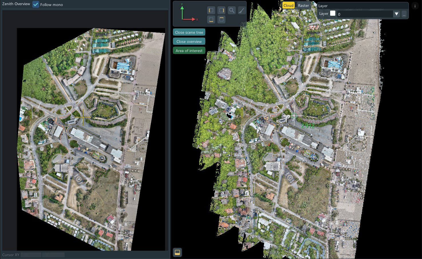
Points that read as surfaces
Seen at an angle, the cloud is drawn with Gaussian splatting: each point becomes a small surface element, so a thin cloud reads as a continuous surface. It is only a way of looking: measurements and drawing are unchanged.
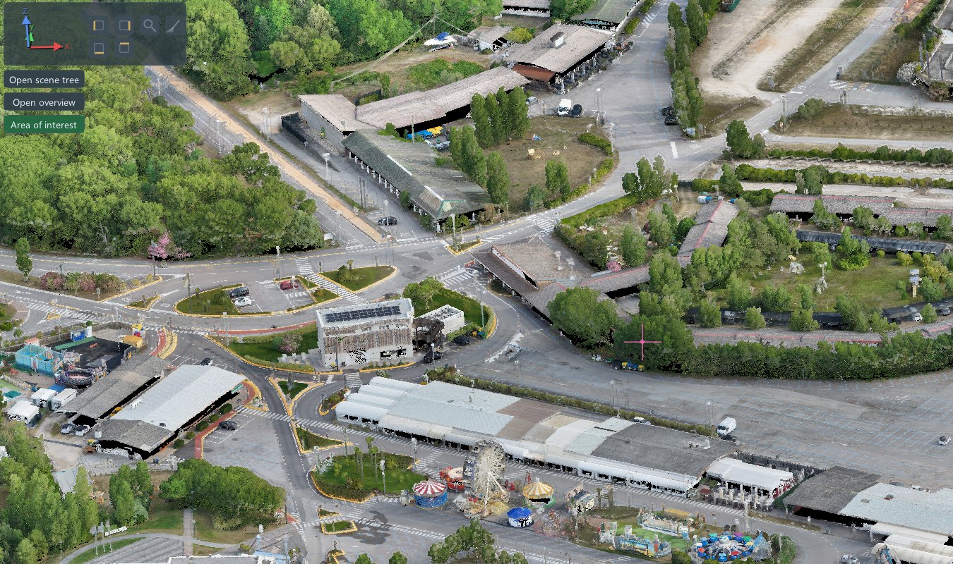
The height under the cursor
A longitudinal profile and a cross section follow the cursor, four metres wide and ten centimetres thick. The kerb, the step, the edge of a roof are there before you click.
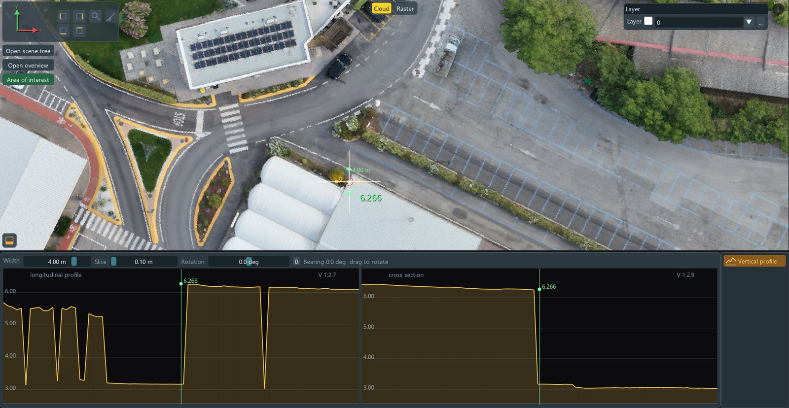
A loupe beside the mark
Next to the cursor, a loupe shows the section of the surface the mark is resting on, with its height. On an ordinary screen you always know whether you are on the ground, on a car or on a roof.
Multiview: the same point from other angles
While you click in the main view, two more windows look at the same point from 45 degrees above, from different sides. The vertex appears in all of them: the ridge, the corner of the eave, the line hidden under a tree are placed with three views instead of one.
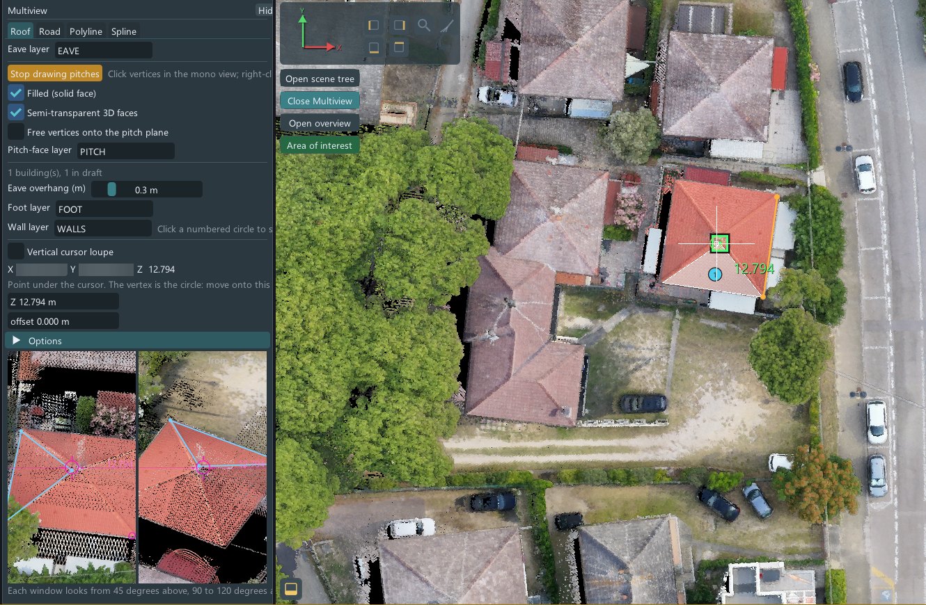
Pitch by pitch
The roof is drawn face by face. Each vertex takes its height from the cloud; the faces close on one another, and the semi-transparent pitches let you see the points underneath while you draw.
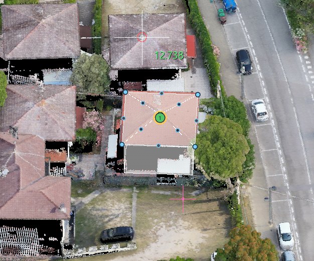
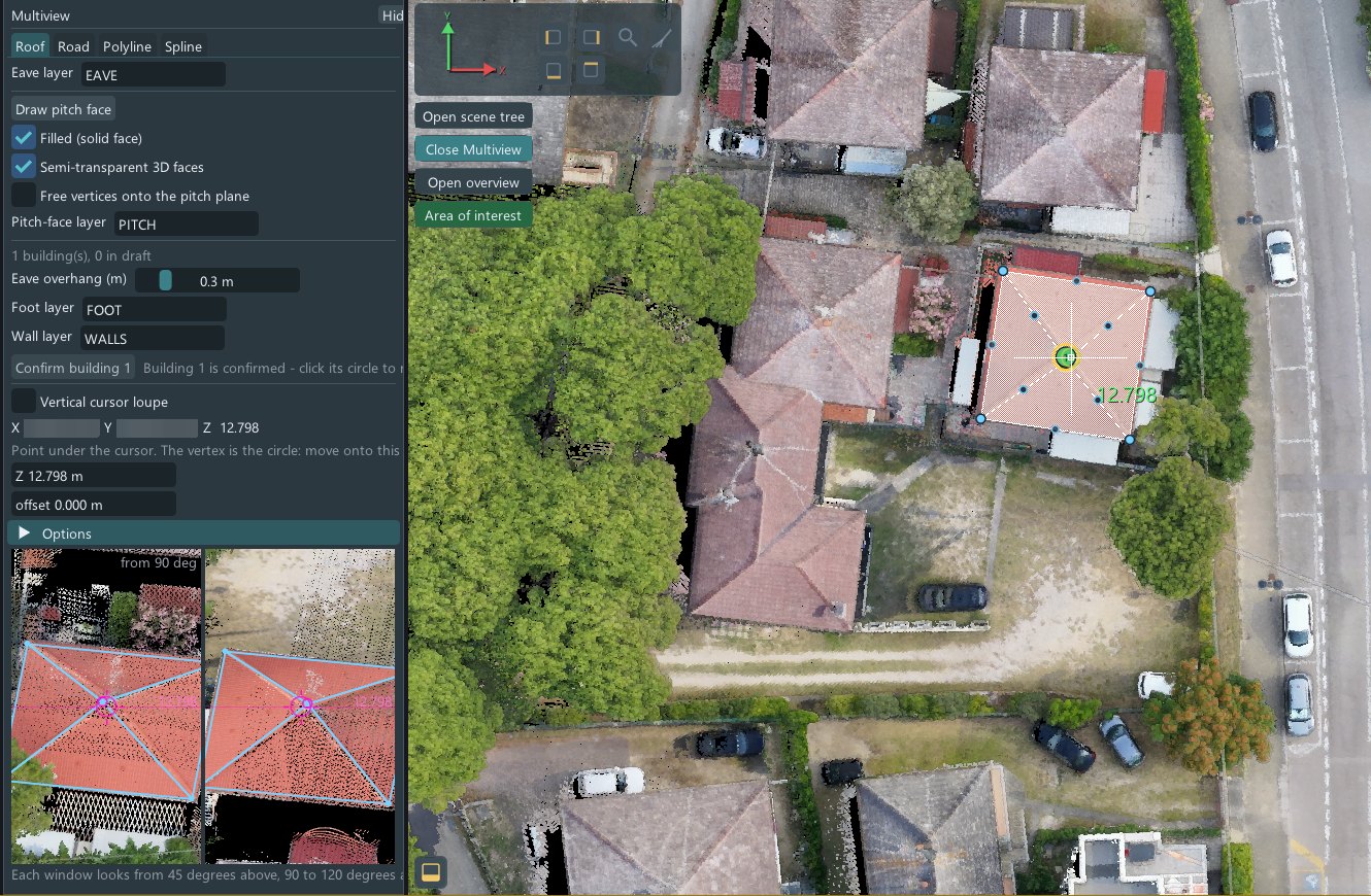
The building, confirmed
From the pitches the program derives the eave outline with its overhang, the foot of the building and the walls, each on its own layer. One confirmation, and the building is complete in the drawing.
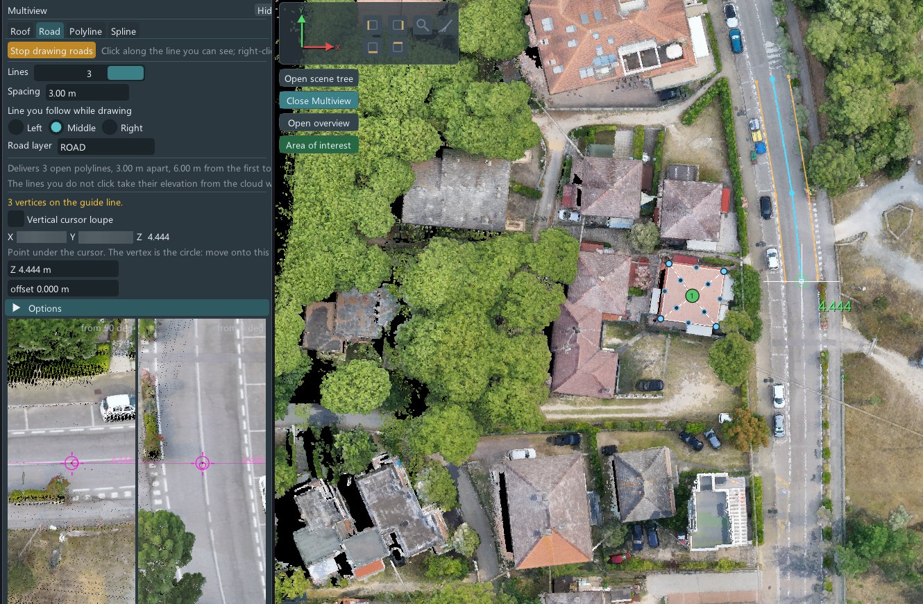
And the roads
The road tool follows the line you see and delivers parallel lines at the spacing you choose, here three lines three metres apart. Their heights, again, come from the cloud.
Where it leads: the whole map
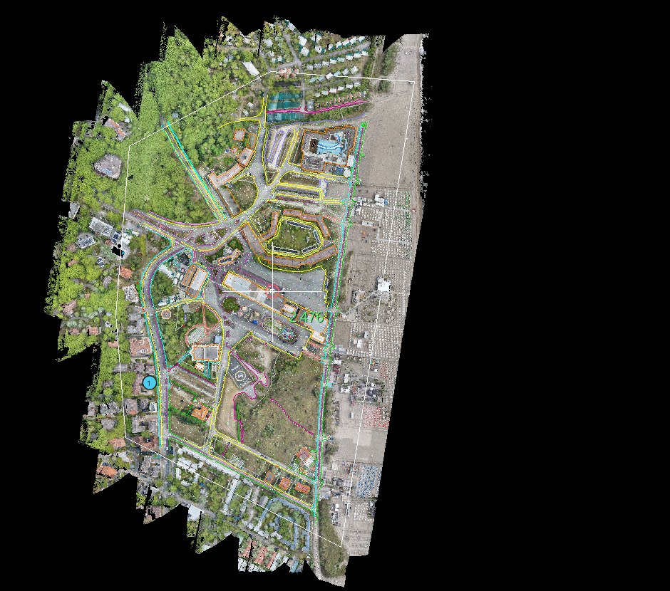
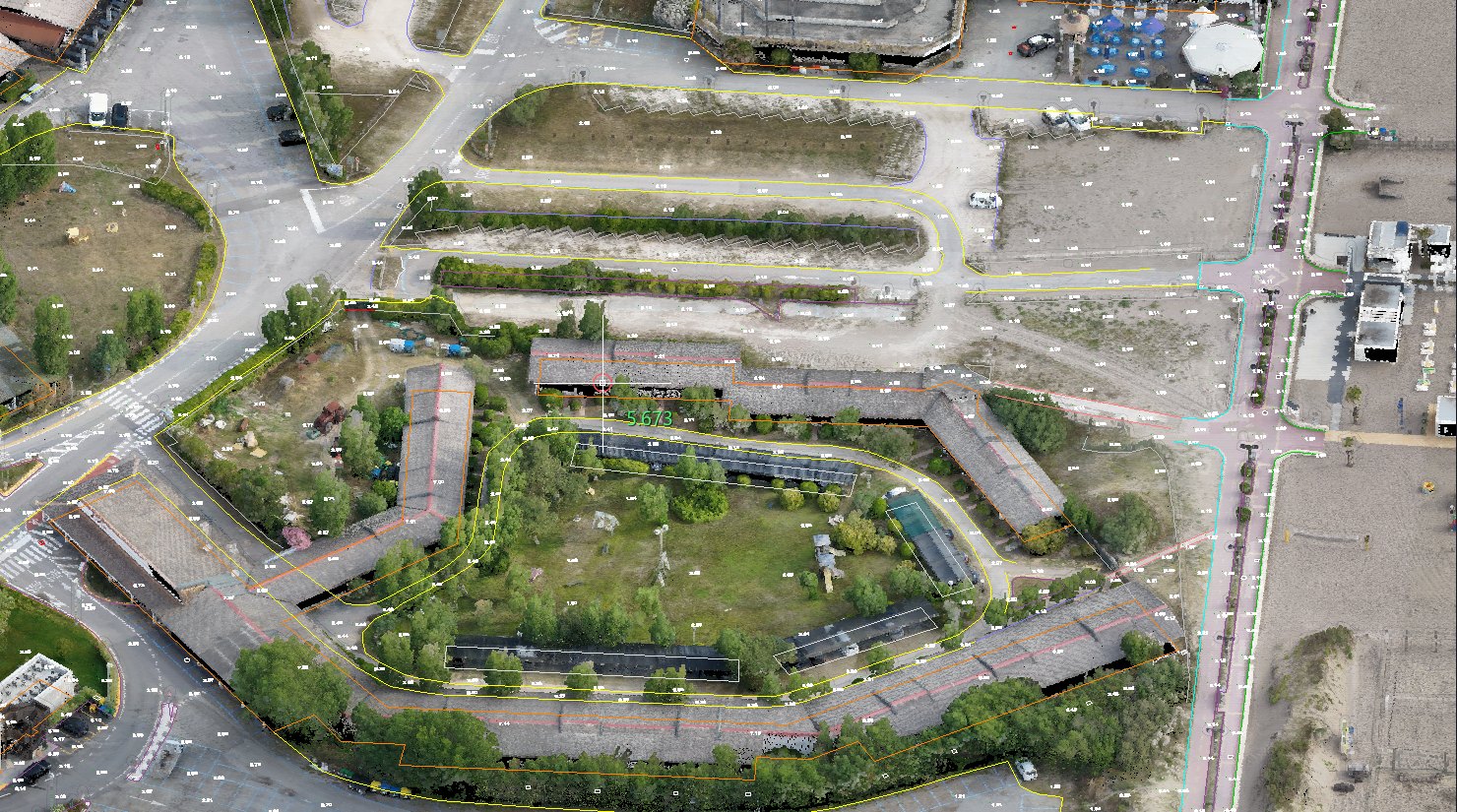
Building after building, road after road, the job becomes the map of the area: road edges and kerbs, buildings, green areas, spot heights, all drawn by hand the way a photogrammetrist draws, and every line sitting on the points of the cloud.
Checked, the way you prefer
The drawing is the same whichever way it was made. It can be reviewed in mono, with the loupe and Multiview, or in stereo by whoever works that way: the same lines, seen in depth on the same points.